Step 1
Choose the tank shape.
Open the ‘Configurator’ tab in the top bar. At the top of the panel on the left is ‘Tank shape’: ‘Rectangular’ or ‘Cylindrical’.
This guide follows the most common tank, the rectangular bolted panel tank. Choose ‘Rectangular’.
Step 2
Enter the tank size in panels.
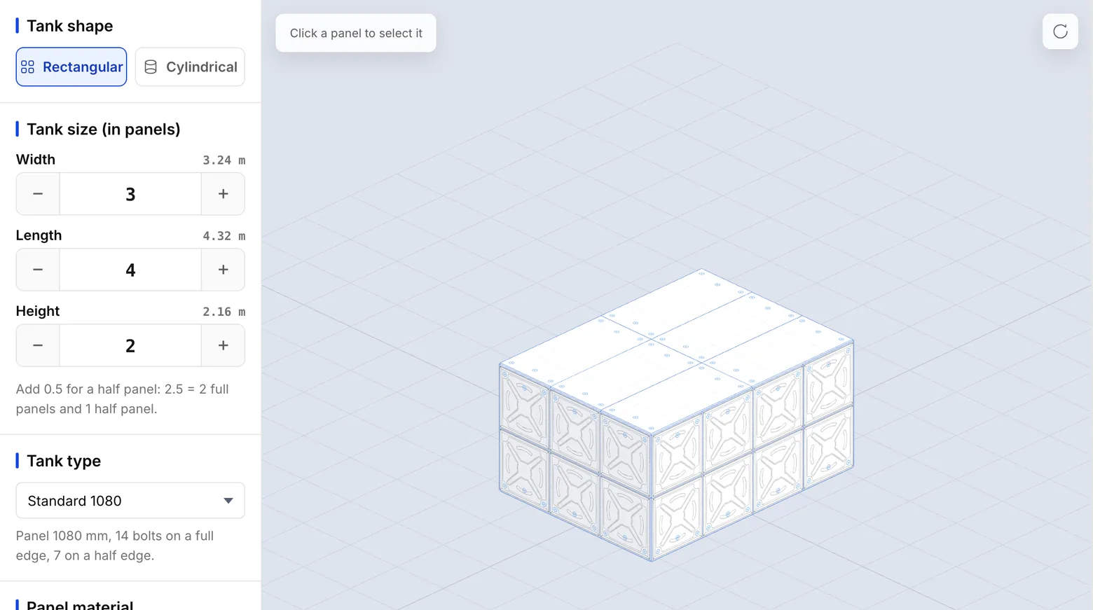
The ‘Tank size (in panels)’ card has three fields: ‘Width’, ‘Length’ and ‘Height’. You type a number of panels in each, not metres.
For a half panel, add .5: 2.5 means two full panels and one half panel. Each press of the plus or minus button beside a field adds or removes a half panel as well.
When you change a dimension, the model rebuilds by itself. There is no button to press.
What you should see
Beside each field's name its length in metres is shown, for example 3.24 m for 3 panels.
Step 3
Choose the tank type and the material.
In the ‘Tank type’ list, choose one of your company's types. Underneath, it shows the type's panel size and bolt count, for example ‘Panel 1080 mm, 14 bolts on a full edge, 7 on a half edge.’
Choose the material in the ‘Panel material’ card. This list holds the materials defined in the tank type.
The same panel has ‘Floor type’ (‘Flat floor’ or ‘Domed floor’) and ‘Bracing’ (‘No bracing’, ‘Internal bracing’ or ‘External bracing’). Choose what the order says.
What you should see
The ‘Tank summary’ card updates the size, the volume and the total number of panels.
Step 4
Choose what the connection is for, its type and its size.
In ‘Add a connection’ on the right, choose what the connection is for: ‘Inlet’, ‘Outlet’, ‘Overflow’, ‘Drain’, ‘Level’ or ‘Manhole’.
In the ‘Connection type’ list below it, choose how it is made: ‘Flanged (PN10)’, ‘Flanged (PN16)’, ‘Threaded (BSP)’ or ‘Wafer’.
In the ‘Connection size (DN)’ list, choose the size. The list comes from your tank type's table of sizes. A level connection is always ½" (DN15).
Step 5
Place the connection by clicking on the model.
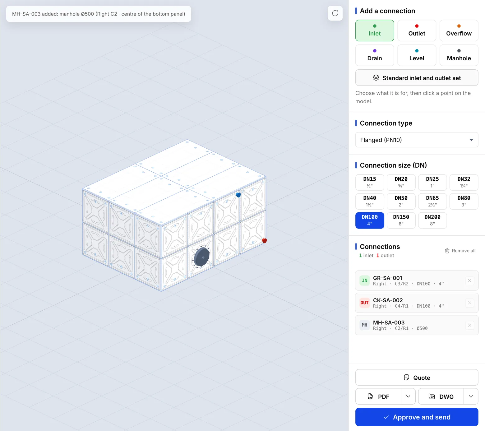
Move the mouse over the model. A small box names the point under the pointer and the connection that will be added. Click where the connection belongs.
A manhole goes only in a bottom row panel of a side wall. A level goes only on a side wall.
Every connection you add appears in the ‘Connections’ list, with the wall and the panel it sits on. Remove a wrong one with the delete button on its row.
What you should see
The connection shows on the model and joins the list.
Step 6
Add the standard inlet and outlet set in one click.
Most tanks have the same connections on one line. Choose ‘Standard inlet and outlet set’ among the connection kinds and click a point on a side wall.
A level (½"), a filling inlet, an outlet, an overflow and a drain (2" threaded) go on that panel line together.
What you should see
Five connections join the list at once.
Step 7
Approve the job.
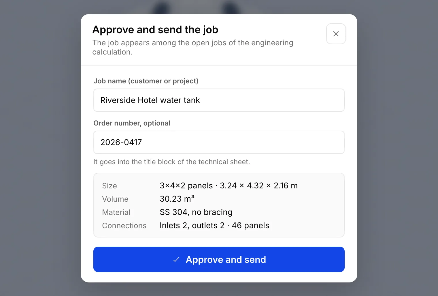
When the tank is ready, press ‘Approve and send’ at the bottom right. The ‘Approve and send the job’ window opens.
In ‘Job name (customer or project)’, type a name you will recognise, such as the customer's name. In ‘Order number, optional’ you can type the order number; it goes into the title block of the technical sheet.
Check the size, the material and the number of connections in the window's summary. If they are right, press ‘Approve and send’ in the window.
What you should see
A notice at the bottom says the job has gone to the engineering calculation, with the button ‘Open the engineering calculation’.
Step 8
Open the engineering calculation.
Press ‘Open the engineering calculation’ in the notice. The engineering calculation opens with this job.
If you missed the notice, open the ‘Engineering calculation’ tab in the top bar, find your job in the ‘Open jobs’ list and press ‘Open calculation’.
What you should see
The job shrinks to one line starting ‘Job:’ at the top of the page, and the results open below it. For another job, press ‘Change’ on that line.
Step 9
Check the approved job and the calculation options.
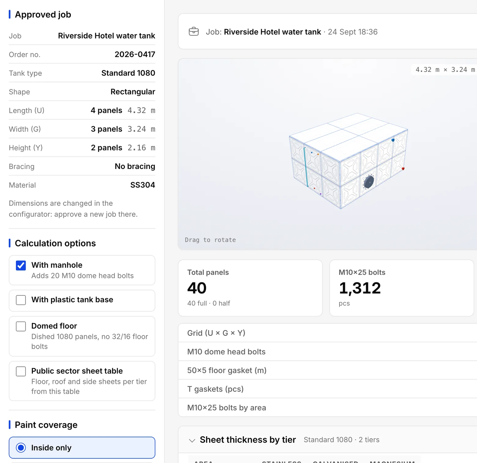
The ‘Approved job’ card shows the tank's definition: tank type, job, order number, size, bracing and material. These values cannot be changed here. If a dimension is wrong, correct it in the configurator and approve a new job.
The ‘Calculation options’ concern the calculation only, such as ‘With manhole’, ‘Domed floor’, ‘Public sector sheet table’ and ‘Paint coverage’. When you change one, the results are calculated again.
Step 10
Read the results.
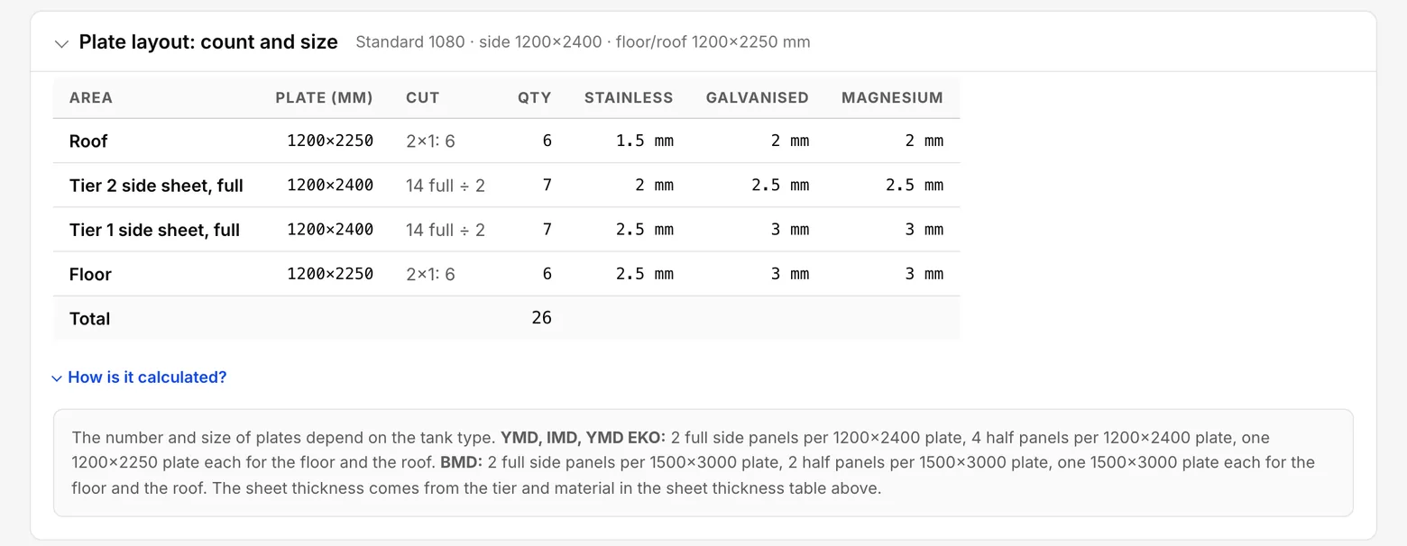
At the top are the big figures: the volume, the total number of panels (full and half), the number of bolts and the length of gasket.
Tables follow underneath: the panel breakdown, the sheet thicknesses, the bolt and gasket detail, and the front and side views.
If you want to know where a figure comes from, open the ‘How is it calculated?’ box under the table. It starts closed; open it to see the rule and the values used.
Step 11
Take the documents.
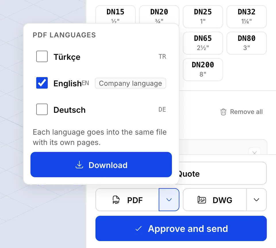
The configurator has two buttons: ‘PDF’ downloads the A0 technical drawing sheet and ‘DWG’ the technical drawing as a DXF file.
In the engineering calculation, the ‘Export’ card has three buttons: ‘Export to Excel’ downloads the Excel analysis, ‘Connections PDF’ the connections sheet, and ‘Print / PDF’ prints the page.
Each button gives you the document in your company's language in one click, without asking anything.
If you need another language, press the small arrow beside the button. For ‘PDF’ and ‘Connections PDF’ you can tick several languages and press ‘Download’: one file, with every sheet in each ticked language in turn. For ‘DWG’ and ‘Export to Excel’ you choose one language. ‘Print / PDF’ has no language choice; it prints the page in the language on the screen.
Once you have downloaded another language from the arrow, the button shows that language's code, EN for example, and one click gives that language until you reload the page. After a reload the button gives your company's language again.
What you should see
The file lands in your Downloads folder.
Step 12
Print the results.
‘Print / PDF’ in the engineering calculation fits the results onto one page and opens the print dialogue.
Choose your printer there. If you want a PDF file instead of paper, choose to save as PDF as the destination.
The same button works in the desktop application. You can also use ‘Print…’ in the ‘File’ menu.
What you should see
The print dialogue shows the results on one page.
Stuck somewhere? Write to us and we will try to answer the same day: contact@fabrikode.com